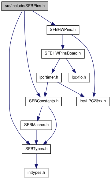
SFBPins.h File Reference
Definitions of the programmer visible 'pins' in SFB. More...
#include "SFBTypes.h"
#include "SFBConstants.h"
#include "SFBHWPins.h"
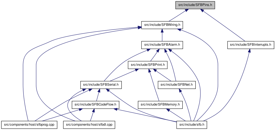
Go to the source code of this file.
Data Structures | |
| struct | PinInfo_s |
| A description of a single SFB-programmer-visible hardware pin. More... | |
Defines | |
| #define | NOT_A_PIN 99 |
| #define | NOT_A_PORT 99 |
| #define | SFB_GET_PIN_PORT_AND_MASK(sfbPin, infoVar, portVar, maskVar) |
| Given a virtual pin 'sfbPin' (which may be an 'Arduino alias'), set portVar to the port number and maskVar (u32) to the bit mask for that virtual pin. | |
| #define | SFB_UNALIAS_PIN(sfbPin) ((pinInfoMap[sfbPin].aliasMode >= ALIAS_COUNT)?pinInfoMap[sfbPin].aliasMode:(sfbPin)) |
| Given a legal pin 'sfbPin' (which may be an 'Arduino alias'), return the unaliased underlying pin number. | |
| #define | SFB_GET_UNALIASED_PIN_PORT_AND_MASK(sfbPin, portVar, maskVar) |
| Given an 'sfbPin' -- which CANNOT be an 'Arduino alias' -- set portVar (u32) to the port number and maskVar (u32) to the bit mask for that pin. | |
| #define | GET_SKETCH_FLAG(sfbPin) ((pinSketchMap[(sfbPin)>>5]>>((sfbPin)&31))&1) |
| #define | SET_SKETCH_FLAG(sfbPin) (pinSketchMap[(sfbPin)>>5] |= 1<<((sfbPin)&31)) |
| #define | CLR_SKETCH_FLAG(sfbPin) (pinSketchMap[(sfbPin)>>5] &= ~(1<<((sfbPin)&31))) |
| #define | PULLUP_ONLY 0 |
| Code to setPinResistor that enables the internal pullup. | |
| #define | NEITHER_PULLUP_NOR_PULLDOWN 2 |
| Code to setPinResistor that disables both the internal pullup and pulldown resistors. | |
| #define | PULLDOWN_ONLY 3 |
| Code to setPinResistor that enables the internal down. | |
Typedefs | |
| typedef struct PinInfo_s | PinInfo_t |
Enumerations | |
| enum | { FACE_D0_PIN = 0, FACE_D1_PIN = 1, FACE_D2_PIN = 2, FACE_D3_PIN = 3, FACE_RX_PIN = 4, FACE_TX_PIN = 5, FACE_VIN_ENABLE_PIN = 6, FACE_VOUT_ENABLE_PIN = 7, FACE_ISENSE_PIN = 8, FACE_LED_PIN = 9, FACE_SIDE_LED_PIN = 10, FACE_PIN_COUNT = 11 } |
| enum | { ARDUINO_RX = 0, ARDUINO_TX = 1, ARDUINO_DIGITAL_PIN2 = 2, ARDUINO_DIGITAL_PIN3 = 3, ARDUINO_DIGITAL_PIN4 = 4, ARDUINO_DIGITAL_PIN5 = 5, ARDUINO_DIGITAL_PIN6 = 6, ARDUINO_DIGITAL_PIN7 = 7, ARDUINO_DIGITAL_PIN8 = 8, ARDUINO_DIGITAL_PIN9 = 9, ARDUINO_DIGITAL_PIN10 = 10, ARDUINO_DIGITAL_PIN11 = 11, ARDUINO_DIGITAL_PIN12 = 12, ARDUINO_DIGITAL_PIN13 = 13, ARDUINO_ANALOG_PIN1 = 14, ARDUINO_ANALOG_PIN2 = 15, ARDUINO_ANALOG_PIN3 = 16, ARDUINO_ANALOG_PIN4 = 17, ARDUINO_ANALOG_PIN5 = 18, ARDUINO_ANALOG_PIN6 = 19, NORTH_BASE_PIN = 20, NORTH_D0_PIN = NORTH_BASE_PIN+FACE_D0_PIN, NORTH_D1_PIN = NORTH_BASE_PIN+FACE_D1_PIN, NORTH_D2_PIN = NORTH_BASE_PIN+FACE_D2_PIN, NORTH_D3_PIN = NORTH_BASE_PIN+FACE_D3_PIN, NORTH_RX_PIN = NORTH_BASE_PIN+FACE_RX_PIN, NORTH_TX_PIN = NORTH_BASE_PIN+FACE_TX_PIN, NORTH_VIN_ENABLE_PIN = NORTH_BASE_PIN+FACE_VIN_ENABLE_PIN, NORTH_VOUT_ENABLE_PIN = NORTH_BASE_PIN+FACE_VOUT_ENABLE_PIN, NORTH_ISENSE_PIN = NORTH_BASE_PIN+FACE_ISENSE_PIN, NORTH_LED_PIN = NORTH_BASE_PIN+FACE_LED_PIN, NORTH_SIDE_LED_PIN = NORTH_BASE_PIN+FACE_SIDE_LED_PIN, SOUTH_BASE_PIN = 31, SOUTH_D0_PIN = SOUTH_BASE_PIN+FACE_D0_PIN, SOUTH_D1_PIN = SOUTH_BASE_PIN+FACE_D1_PIN, SOUTH_D2_PIN = SOUTH_BASE_PIN+FACE_D2_PIN, SOUTH_D3_PIN = SOUTH_BASE_PIN+FACE_D3_PIN, SOUTH_RX_PIN = SOUTH_BASE_PIN+FACE_RX_PIN, SOUTH_TX_PIN = SOUTH_BASE_PIN+FACE_TX_PIN, SOUTH_VIN_ENABLE_PIN = SOUTH_BASE_PIN+FACE_VIN_ENABLE_PIN, SOUTH_VOUT_ENABLE_PIN = SOUTH_BASE_PIN+FACE_VOUT_ENABLE_PIN, SOUTH_ISENSE_PIN = SOUTH_BASE_PIN+FACE_ISENSE_PIN, SOUTH_LED_PIN = SOUTH_BASE_PIN+FACE_LED_PIN, SOUTH_SIDE_LED_PIN = SOUTH_BASE_PIN+FACE_SIDE_LED_PIN, EAST_BASE_PIN = 42, EAST_D0_PIN = EAST_BASE_PIN+FACE_D0_PIN, EAST_D1_PIN = EAST_BASE_PIN+FACE_D1_PIN, EAST_D2_PIN = EAST_BASE_PIN+FACE_D2_PIN, EAST_D3_PIN = EAST_BASE_PIN+FACE_D3_PIN, EAST_RX_PIN = EAST_BASE_PIN+FACE_RX_PIN, EAST_TX_PIN = EAST_BASE_PIN+FACE_TX_PIN, EAST_VIN_ENABLE_PIN = EAST_BASE_PIN+FACE_VIN_ENABLE_PIN, EAST_VOUT_ENABLE_PIN = EAST_BASE_PIN+FACE_VOUT_ENABLE_PIN, EAST_ISENSE_PIN = EAST_BASE_PIN+FACE_ISENSE_PIN, EAST_LED_PIN = EAST_BASE_PIN+FACE_LED_PIN, EAST_SIDE_LED_PIN = EAST_BASE_PIN+FACE_SIDE_LED_PIN, WEST_BASE_PIN = 53, WEST_D0_PIN = WEST_BASE_PIN+FACE_D0_PIN, WEST_D1_PIN = WEST_BASE_PIN+FACE_D1_PIN, WEST_D2_PIN = WEST_BASE_PIN+FACE_D2_PIN, WEST_D3_PIN = WEST_BASE_PIN+FACE_D3_PIN, WEST_RX_PIN = WEST_BASE_PIN+FACE_RX_PIN, WEST_TX_PIN = WEST_BASE_PIN+FACE_TX_PIN, WEST_VIN_ENABLE_PIN = WEST_BASE_PIN+FACE_VIN_ENABLE_PIN, WEST_VOUT_ENABLE_PIN = WEST_BASE_PIN+FACE_VOUT_ENABLE_PIN, WEST_ISENSE_PIN = WEST_BASE_PIN+FACE_ISENSE_PIN, WEST_LED_PIN = WEST_BASE_PIN+FACE_LED_PIN, WEST_SIDE_LED_PIN = WEST_BASE_PIN+FACE_SIDE_LED_PIN, BODY_SWITCH0_PIN = 64, BODY_RGB_RED_PIN = 65, BODY_RGB_GREEN_PIN = 66, BODY_RGB_BLUE_PIN = 67, BODY_EEPROM_SSEL1_PIN = 68, BODY_EEPROM_SCK1_PIN = 69, BODY_EEPROM_MISO1_PIN = 70, BODY_EEPROM_MOSI1_PIN = 71, BODY_AMUX_READ_PIN = 72, BODY_AMUX_SELA_PIN = 73, BODY_AMUX_SELB_PIN = 74, BODY_AMUX_SELC_PIN = 75, VIRTUAL_PIN_COUNT = 76, ALIAS_COUNT = 20, FIRST_SFB_PIN = 20 } |
| enum | { PIN_SKETCH_MAP_WORDS = (VIRTUAL_PIN_COUNT+31)/32 } |
Functions | |
| int | pinInFace (int facePin, int face) |
| Find the pin number of a specific pin location within a given face. | |
| bool | isFacePin (int pin, u8 *face=0, u8 *facePin=0) |
Determine if a given a pin is associated with one of the faces and return true if and only if it is. | |
| void | reflexDigitalWrite (int sfbPin, int value) |
| void | implDigitalWrite (int sfbPin, int value) |
| int | reflexDigitalRead (int sfbPin) |
| int | implDigitalRead (int sfbPin) |
| void | reflexPinMode (int sfbPin, int mode) |
| void | implPinMode (int sfbPin, int mode) |
| void | pins_startup_initialization () |
| void | setPinResistor (int sfbPin, int pullupDownCode) |
| Enable or disable the internal pull-up or pull-down resistors on GPIO pin sfbPin. | |
| void | reflexSetPinResistor (int sfbPin, int pullupDownCode) |
| void | implSetPinResistor (int sfbPin, int pullupDownCode) |
Variables | |
| struct PinInfo_s | aligned |
| A description of a single SFB-programmer-visible hardware pin. | |
| PinInfo_t | pinInfoMap [VIRTUAL_PIN_COUNT] |
| u32 | pinSketchMap [PIN_SKETCH_MAP_WORDS] |
Detailed Description
Definitions of the programmer visible 'pins' in SFB.
- Date:
- (C) 2008 All rights reserved.
- Code License:
- The GNU Lesser General Public License
- License Note:
- All code samples shown in documentation are placed into the public domain.
Define Documentation
| #define SFB_GET_PIN_PORT_AND_MASK | ( | sfbPin, | |||
| infoVar, | |||||
| portVar, | |||||
| maskVar | ) |
Value:
do {                                                           \
   (infoVar) = pinInfoMap[sfbPin];                              \
   if ((infoVar).aliasMode >= ALIAS_COUNT) {                    \
     (sfbPin) = (infoVar).aliasMode;                            \
     (infoVar) = pinInfoMap[sfbPin];                            \
   }                                                            \
   (portVar) = (infoVar).portNumber;                            \
   (maskVar) = 1UL<<(infoVar).bitNumber;                        \
 } while (0)
Will also UPDATE sfbPin if necessary, for it to have a non-alias value! infoVar (u32) is scratch storage.
| #define SFB_GET_UNALIASED_PIN_PORT_AND_MASK | ( | sfbPin, | |||
| portVar, | |||||
| maskVar | ) |
Value:
do {                                                              \
   (portVar) = pinInfoMap[sfbPin].portNumber;                       \
   (maskVar) = 1UL<<pinInfoMap[sfbPin].bitNumber;                   \
  } while (0)
(Afterwards, portVar and maskVar can be passed to the SFB_PORT_SET_BIT_MASK, SFB_PORT_CLR_BIT_MASK, and SFB_PORT_WRITE_BIT_MASK macros for fast GPIO pin setting. Undefined if 'sfbPin' is < FIRST_SFB_PIN or >= VIRTUAL_PIN_COUNT. 'sfbPin' is evaluated multiple times and so should not have side effects.
- Since:
- 0.9.17
| #define SFB_UNALIAS_PIN | ( | sfbPin | ) | ((pinInfoMap[sfbPin].aliasMode >= ALIAS_COUNT)?pinInfoMap[sfbPin].aliasMode:(sfbPin)) |
Given a legal pin 'sfbPin' (which may be an 'Arduino alias'), return the unaliased underlying pin number.
Undefined if sfbPin is not a legal pin (in the range 0..VIRTUAL_PIN_COUNT-1 inclusive).
- Since:
- 0.9.17
Enumeration Type Documentation
| anonymous enum |
- Enumerator:
| anonymous enum |
- Enumerator:
-
ARDUINO_RX Aliased to NORTH_RX_PIN. ARDUINO_TX Aliased to NORTH_TX_PIN. ARDUINO_DIGITAL_PIN2 Aliased to NORTH_D0_PIN. ARDUINO_DIGITAL_PIN3 Aliased to NORTH_D1_PIN. ARDUINO_DIGITAL_PIN4 Aliased to NORTH_D2_PIN. ARDUINO_DIGITAL_PIN5 Aliased to NORTH_D3_PIN. ARDUINO_DIGITAL_PIN6 Aliased to SOUTH_D0_PIN. ARDUINO_DIGITAL_PIN7 Aliased to SOUTH_D1_PIN. ARDUINO_DIGITAL_PIN8 Aliased to SOUTH_D2_PIN. ARDUINO_DIGITAL_PIN9 Aliased to SOUTH_D3_PIN. ARDUINO_DIGITAL_PIN10 Aliased to EAST_D0_PIN. ARDUINO_DIGITAL_PIN11 Aliased to EAST_D1_PIN. ARDUINO_DIGITAL_PIN12 Aliased to EAST_D2_PIN. ARDUINO_DIGITAL_PIN13 Aliased to BODY_RGB_RED_PIN. ARDUINO_ANALOG_PIN1 Aliased to NORTH_ISENSE_PIN. ARDUINO_ANALOG_PIN2 Aliased to SOUTH_ISENSE_PIN. ARDUINO_ANALOG_PIN3 Aliased to EAST_ISENSE_PIN. ARDUINO_ANALOG_PIN4 Aliased to WEST_ISENSE_PIN. NORTH_D0_PIN Pin 20: D0 on the North face. NORTH_D1_PIN Pin 21: D1 on the North face. NORTH_D2_PIN Pin 22: D2 on the North face. NORTH_D3_PIN Pin 23: D3 on the North face. NORTH_RX_PIN Pin 24: Serial Rx on the North face. NORTH_TX_PIN Pin 25: Serial Tx on the North face. NORTH_VIN_ENABLE_PIN Pin 26: Power input enable on the North face. NORTH_VOUT_ENABLE_PIN Pin 27: Power output enable on the North face. NORTH_ISENSE_PIN Pin 28: ADC current sense on the North face. NORTH_LED_PIN Pin 29: Active-low LED on the North face. NORTH_SIDE_LED_PIN Pin 30: Active-low side LED on the North face. SOUTH_D0_PIN Pin 31: D0 on the South face. SOUTH_D1_PIN Pin 32: D1 on the South face. SOUTH_D2_PIN Pin 33: D2 on the South face. SOUTH_D3_PIN Pin 34: D3 on the South face. SOUTH_RX_PIN Pin 35: Serial Rx on the South face. SOUTH_TX_PIN Pin 36: Serial Tx on the South face. SOUTH_VIN_ENABLE_PIN Pin 37: Power input enable on the South face. SOUTH_VOUT_ENABLE_PIN Pin 38: Power output enable on the South face. SOUTH_ISENSE_PIN Pin 39: ADC current sense on the South face. SOUTH_LED_PIN Pin 40: Active-low LED on the South face. SOUTH_SIDE_LED_PIN Pin 41: Active-low side LED on the South face. EAST_D0_PIN Pin 42: D0 on the East face. EAST_D1_PIN Pin 43: D1 on the East face. EAST_D2_PIN Pin 44: D2 on the East face. EAST_D3_PIN Pin 45: D3 on the East face. EAST_RX_PIN Pin 46: Serial Rx on the East face. EAST_TX_PIN Pin 47: Serial Tx on the East face. EAST_VIN_ENABLE_PIN Pin 48: Power input enable on the East face. EAST_VOUT_ENABLE_PIN Pin 49: Power output enable on the East face. EAST_ISENSE_PIN Pin 50: ADC current sense on the East face. EAST_LED_PIN Pin 51: Active-low LED on the East face. EAST_SIDE_LED_PIN Pin 52: Active-low side LED on the East face. WEST_D0_PIN Pin 53: D0 on the West face. WEST_D1_PIN Pin 54: D1 on the West face. WEST_D2_PIN Pin 55: D2 on the West face. WEST_D3_PIN Pin 56: D3 on the West face. WEST_RX_PIN Pin 57: Serial Rx on the West face. WEST_TX_PIN Pin 58: Serial Tx on the West face. WEST_VIN_ENABLE_PIN Pin 59: Power input enable on the West face. WEST_VOUT_ENABLE_PIN Pin 60: Power output enable on the West face. WEST_ISENSE_PIN Pin 61: ADC current sense on the West face. WEST_LED_PIN Pin 62: Active-low LED on the West face. WEST_SIDE_LED_PIN Pin 63: Active-low side LED on the West face. BODY_SWITCH0_PIN Pin 64: Active low button pressed. BODY_RGB_RED_PIN Pin 65: Active low center RGB red LED. BODY_RGB_GREEN_PIN Pin 66: Active low center RGB green LED. BODY_RGB_BLUE_PIN Pin 67: Active low center RGB blue LED. BODY_EEPROM_SSEL1_PIN Pin 68: EEPROM SSEL. BODY_EEPROM_SCK1_PIN Pin 69: EEPROM SCK. BODY_EEPROM_MISO1_PIN Pin 70: EEPROM MISO. BODY_EEPROM_MOSI1_PIN Pin 71: EEPROM MOSI. BODY_AMUX_READ_PIN Pin 72: Analog MUX Common read. BODY_AMUX_SELA_PIN Pin 73: Analog MUX Select A. BODY_AMUX_SELB_PIN Pin 74: Analog MUX Select B. BODY_AMUX_SELC_PIN Pin 75: Analog MUX Select C.
Function Documentation
Determine if a given a pin is associated with one of the faces and return true if and only if it is.
Furthermore, if pin is such a 'face pin', this function will also store pin's associated face number, and/or its pin number within that face, through the supplied pointers face and facePin, respectively, if they are non-zero.
This function can be used to invert pinInFace. A code sequence such as the following cannot fail, so long as theFace and thePinInFace start out with legal values:
      u8 theFace = ..;                   // NORTH, SOUTH, EAST, or WEST
      u8 thePinInFace = ..;              // E.g., FACE_LED_PIN, FACE_RX_PIN, etc
      u8 pin = pinInFace(theFace,thePinInFace);
      u8 aFace;
      u8 aPinInFace;
      bool worked = isFacePin(pin, &aFace, &aPinInFace);
      API_ASSERT_TRUE(worked);
      API_ASSERT_EQUAL(aFace,theFace);
      API_ASSERT_EQUAL(aPinInFace,thePinInFace);
But note the reverse is not necessarily true, because of pin aliasing. The following code will violate its assertion and die blinking if 'somePin' is set to an alias of a face pin, such as ARDUINO_TX (which is an alias for NORTH_TX_PIN):
      u8 somePin = ..;
      u8 aFace;
      u8 aPinInFace;
      if (isFacePin(somePin,&aFace,&aPinInFace)) {
        u8 aPin = pinInFace(aPinInFace,aFace);
        API_ASSERT_EQUAL(somePin,aPin);  // WATCH OUT: COULD FAIL!  somePin might be an \e alias for aPin
      }
- Parameters:
-
pin the pin number to analyze face If present and non-zero, a pointer through which to store pin's face number, if this function returns true.facePin If present and non-zero, a pointer through which to store pin's pin-number-within-face, if this function returns true.
- Returns:
trueif pin is a 'face pin',falseotherwise.
- Side Effects:
- The contents pointed to by face and facePin are each written to, if the pointer value is non-zero and pin is a 'face pin'.
- Blinks:
- E_API_BAD_PIN if pin is not a legal pin number
- Since:
- 0.9.10
| int pinInFace | ( | int | facePin, | |
| int | face | |||
| ) |
Find the pin number of a specific pin location within a given face.
Pins that are on faces can be referred to in (at least) two different ways: Directly, by their pin number (such as NORTH_LED_PIN), or indirectly, through the combination of their face (such as NORTH), and a relative 'pin number within face' (such as FACE_LED_PIN). This function takes the latter two pieces of information and produces the first piece. (See isFacePin to go the other way.)
- Example:
      void lightAllFaces(bool on) {                // Set all face LEDs on or off
        for (u32 f = NORTH; f <= WEST; ++f)        // For each face..
          ledSet(pinInFace(FACE_LED_PIN,f),on);    // ..Turn on or off the LED pin within that face
      }
- Parameters:
-
facePin a relative pin number within a face, such as FACE_LED_PIN or FACE_D2_PIN. face a face number, one of NORTH, SOUTH, EAST, or WEST.
- Returns:
- the absolute pin number found at position facePin of the given face.
- Blinks:
- E_API_BAD_FACE if face is not one of the four 'directional' face codes.
- Blinks:
- E_API_MAX_RANGE if facePin is greater than FACE_PIN_COUNT.
- Examples:
- profile2.cpp, profile3.cpp, and qled1.cpp.
| void setPinResistor | ( | int | sfbPin, | |
| int | pullupDownCode | |||
| ) |
Enable or disable the internal pull-up or pull-down resistors on GPIO pin sfbPin.
This function also places sfbPin under sketch control (so the core software won't mess with it).
- Parameters:
-
sfbPin,: The pin to configure pullupDownCode,: One of: PULLUP_ONLY, NEITHER_PULLUP_NOR_PULLDOWN, PULLDOWN_ONLY.
Variable Documentation
A description of a single SFB-programmer-visible hardware pin.
The attribute is added to force word alignment without union shenanigans...